INTERACTIVE ADAS MAP

Click a sensor field. See what we calibrate.

Click a sensor field. See what we calibrate.

Click a sensor field. See what we calibrate.

ADAS calibration is not one procedure. Each camera, radar, lidar, and ultrasonic field has its own target geometry, scan path, and verification code.

ADAS calibration is not one procedure. Each camera, radar, lidar, and ultrasonic field has its own target geometry, scan path, and verification code.

ADAS calibration is not one procedure. Each camera, radar, lidar, and ultrasonic field has its own target geometry, scan path, and verification code.

ADAS systems diagram

CLICK A SYSTEM FIELD

ADAS code map

Select a sensor field in the diagram to view the related calibration and diagnostic function codes Calitech verifies during service.

CAM-TSR · RAD-AEB · LID-SV · USS-PA · BSD-SMR

Codes are service categories used for triage and documentation; OEM scan output confirms vehicle-specific procedures.

ADAS systems diagram

ADAS code map

Tap the full diagram on desktop for interactive codes. On mobile, the key calibration categories are grouped below.

CAM-LDW · CAM-TSR · RAD-ACC · RAD-AEB · SMR-BSD · SMR-RCTA · LID-SV · USS-PA

THE ANATOMY OF SAFETY

Precision in every millisecond.

Precision in every millisecond.

Precision in every millisecond.

Radars

Radars

Radars

Long-range return logic verified against OEM target distance and yaw tolerance.

Long-range return logic verified against OEM target distance and yaw tolerance.

Windshield Cameras

Windshield Cameras

Lane geometry, pitch angle, and focal alignment confirmed after glass replacement.

Lidar Arrays

Lidar Arrays

Near-field spatial mapping checked for centimeter drift before release.

WHAT ADAS CALIBRATION IS

Re-teaching the vehicle where the world is.

Re-teaching the vehicle where the world is.

Re-teaching the vehicle where the world is.

Advanced driver assistance systems rely on cameras, radar, lidar, steering angle sensors, and control modules agreeing on the same geometry. After collision repair, glass replacement, suspension work, alignments, or module replacement, that geometry can drift. Calibration restores the vehicle’s sensor map to OEM reference.

Advanced driver assistance systems rely on cameras, radar, lidar, steering angle sensors, and control modules agreeing on the same geometry. After collision repair, glass replacement, suspension work, alignments, or module replacement, that geometry can drift. Calibration restores the vehicle’s sensor map to OEM reference.

Advanced driver assistance systems rely on cameras, radar, lidar, steering angle sensors, and control modules agreeing on the same geometry. After collision repair, glass replacement, suspension work, alignments, or module replacement, that geometry can drift. Calibration restores the vehicle’s sensor map to OEM reference.

01

Sensor reference

Targets, ride height, alignment values, and module data give every sensor a known starting point.

02

OEM calibration

The system learns precise camera aim, radar angle, sensor range, and control-module thresholds.

03

Safety output

Lane keeping, adaptive cruise, forward collision alerts, blind spot monitoring, and braking logic depend on that geometry being exact.

If the sensor map is wrong, the vehicle can react late, react early, or fail to react at all.

If the sensor map is wrong, the vehicle can react late, react early, or fail to react at all.

THE MARGIN FOR ERROR

14 Millimeters

14 Millimeters

14 Millimeters

The offset required to cause an automatic braking system failure. We recalibrate to zero.

The offset required to cause an automatic braking system failure. We recalibrate to zero.

ZERO OFFSET

OEM DIAGNOSTIC CRITERIA

Calibration is not an estimate.

Calibration is not an estimate.

Calibration is not an estimate.

Every release is checked against OEM scan data, target geometry, environmental conditions, and post-calibration fault logic—not visual approximation.

Every release is checked against OEM scan data, target geometry, environmental conditions, and post-calibration fault logic—not visual approximation.

Every release is checked against OEM scan data, target geometry, environmental conditions, and post-calibration fault logic—not visual approximation.

Criterion

Elite Recalibration Lab

Generic Collision Shop

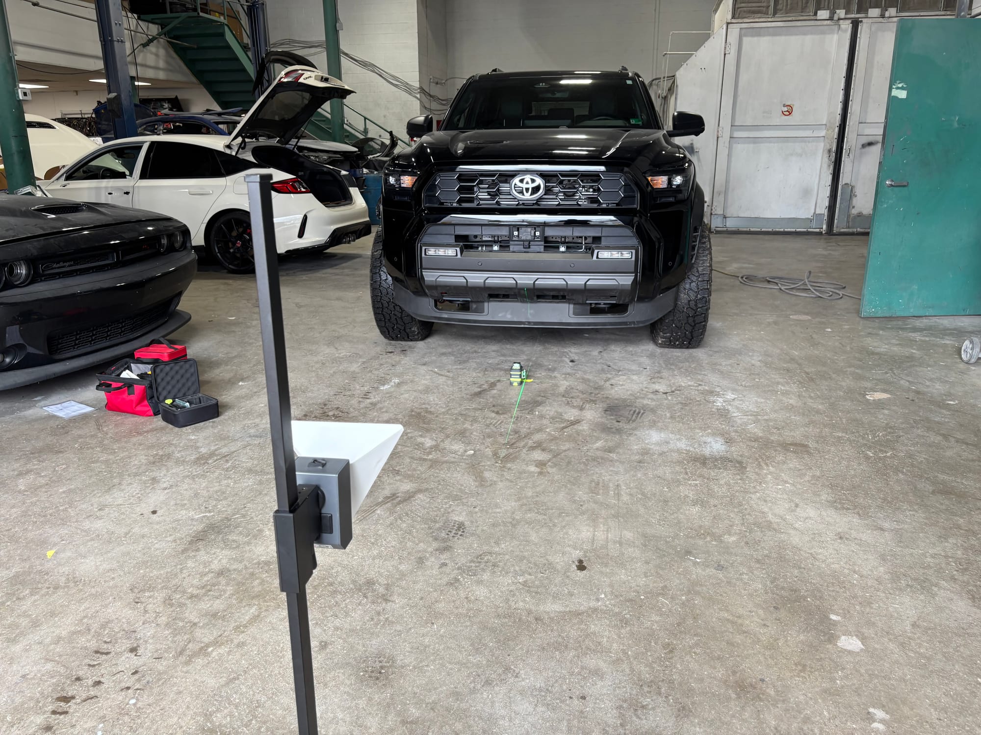
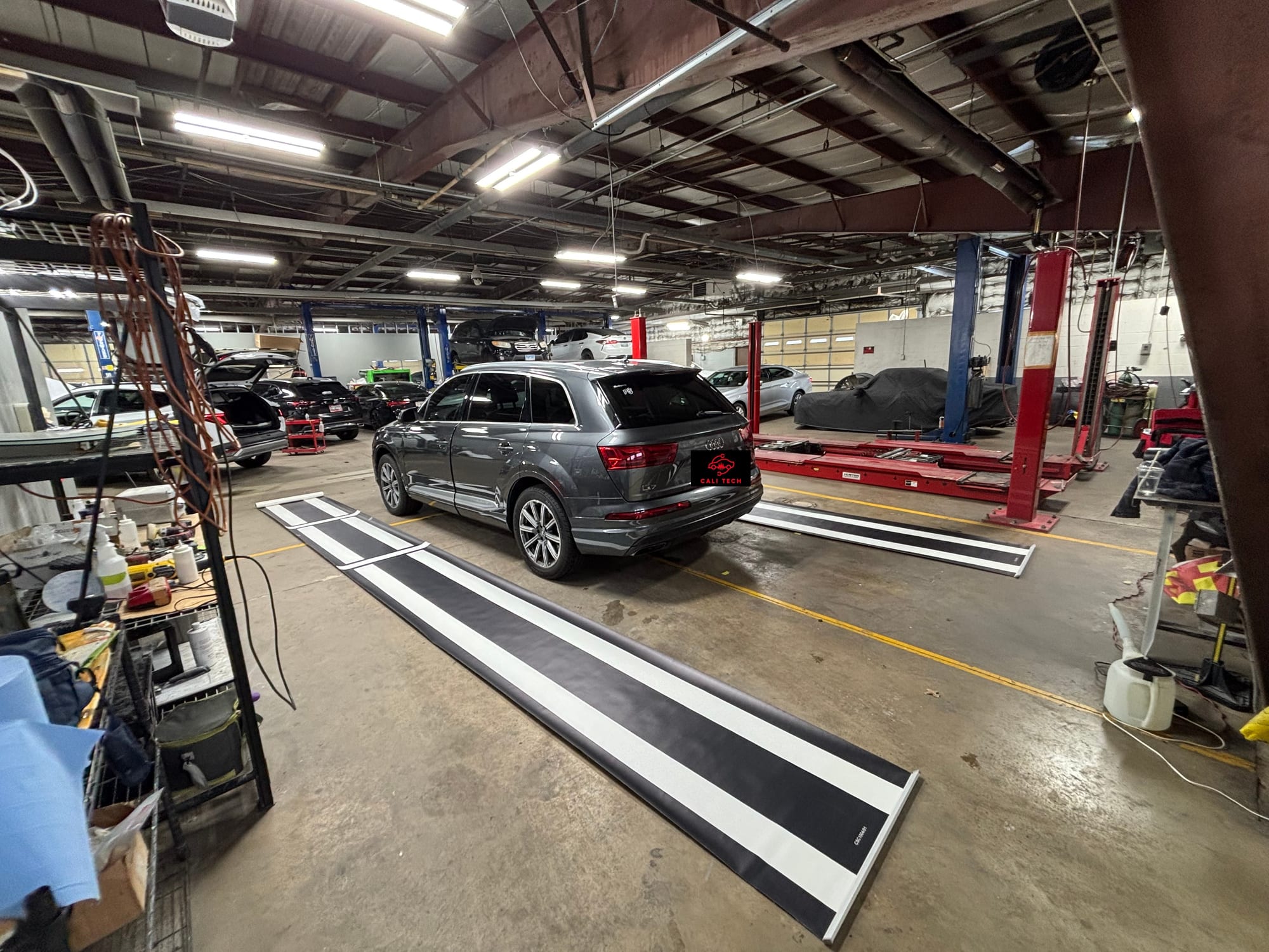
Target geometry

US

OEM distance, height, pitch, yaw, and floor plane verified before scan release.

OEM distance, height, pitch, yaw, and floor plane verified before scan release.

Generic Collision Shop

Visual placement and quick clear procedures.

Scan protocol

US

Pre-scan, calibration, post-scan, and module status stored with every job.

Fault clear without evidence-backed alignment records.

Generic Collision Shop

Environmental control

US

Lighting, level surface, battery support, and target field constraints controlled.

Generic Collision Shop

Workflow adapted to whatever bay is open.